


Custom Implementation
In most cases, the platform integration provided by Soracom allows you to focus on building your application without worrying about how to implement hardware or firmware functionality, or how to decode/encode messages coming from or going to the Soracom LTE-M Button.
However, in some cases, you may prefer to process the messages on your own, such as to build your own interface for configuring and managing buttons, or inspecting packets for troubleshooting.
Below are the technical specifications for how binary data coming from or going to the Soracom LTE-M Button is implemented.
Implementation Overview
The Soracom LTE-M Button is programmed to send messages in a UDP packet using a custom binary data format, allowing it to consume significantly less data compared to other common data formats or protocols and to minimize battery usage. The platform integration provided by Soracom takes care of decoding the binary data from (and encoding binary data responses to) the button into an easier-to-use JSON format.
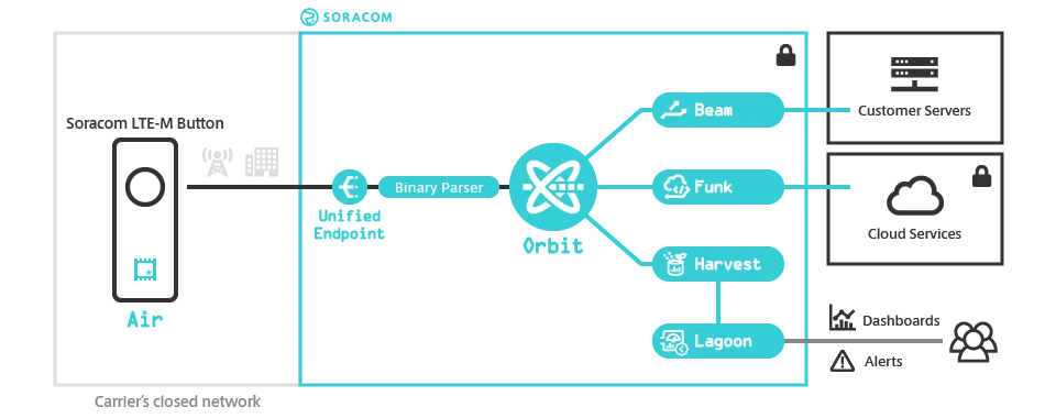
The Soracom LTE-M Button leverages multiple Soracom services in order to provide full platform integration. Messages sent by the button are processed as follows:
-
The button sends a binary message to Unified Endpoint.
-
The binary message is decoded by Binary Parser into JSON using the symbol and message format specifications below.
-
The decoded message is processed by Soracom Orbit in order to update the SIM tags that correspond to the button, allowing you to check button details such as operation mode and battery voltage from the User Console.
-
The JSON data is then sent to any Soracom platform services you have enabled for handling the data, such as Soracom Beam or Soracom Funk for forwarding the message to an external server or cloud function, or Soracom Harvest Data to store the message in Soracom.
-
Finally, if the message sent was a Status message, Soracom Orbit will also check if the button's current configuration matches the configuration you specified. If any changes are required, Soracom Orbit will construct a Set Configuration message using the symbol and message format specification below and send the binary message back to the button to apply the necessary configuration. Otherwise Soracom Orbit simply sends a Server ACK message.
Service Integration
By default, all of the services above (except for Soracom Beam, Soracom Funk, or Soracom Harvest Data) are automatically configured when you create a Soracom LTE-M Button group and should provide enough flexibility for most applications.
However, if you want to build your own system for processing button messages, you may need to manually configure the Binary Parser, Soracom Orbit, and Unified Endpoint settings, or reimplement their functionality using the symbol and message format specifications below, depending on your application requirements. The following table summarizes each of the necessary service configurations:
| Service | Configuration | Function | Can be manually implemented? |
|---|---|---|---|
| [Binary Parser](/docs/groups/binary-parser) | - **Format** - `@soracom.button` | Converts uplink messages from binary to JSON | Yes |
| [Soracom Orbit](/docs/orbit) | - **[Code SRN](/docs/reference/srn)** - `srn:soracom:OP0052363844:g:Soralet:soracom-lte-m-button-configuration/$LATEST`*1\n- **Content Type** - `application/json`\n- **Direction** - Downlink\n- **Use metadata** - Enabled | Updates SIM tags and constructs binary messages to send back to the button | Yes*2, *3 |
| [Unified Endpoint](/docs/unified-endpoint) | - **Format** - Custom\n- **Custom response on success**\n - **Status Code** - `200`\n - **Content Type** - `application/octet-stream`\n - **Skip status code** - Enabled\n- **Custom response on failure**\n - **Status Code** - `400`\n - **Content Type** - `application/octet-stream`\n - **Skip status code** - Enabled | Allows sending downlink messages to the button in binary | No*4 |
*1 - This Soracom Orbit Soralet specified by this Code SRN is officially developed and maintained by Soracom.
*2 - You can use the Soracom API to update SIM tags without using Soracom Orbit.
*3 - You can construct binary messages to send back to your button without using Soracom Orbit. However, if you want to use Soracom Orbit, you must also enable and configure Metadata Service User data.
*4 - Configuring Unified Endpoint is not required but may prevent Set Configuration messages from being delivered correctly.
Uplink and Downlink Message Flow
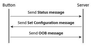
When a button sends an uplink message, it expects a response from the server in order to confirm that the uplink message was successfully received. The server should respond with the Server ACK message. If the server does not respond, the button will assume that the uplink message was not received and attempt to send the message again.

When modifying a button's configuration, the server should first wait for an uplink Status message from the button. Once the server receives the message, it can respond with a Set Configuration message containing the configuration options to apply. The button will send an OOB message to indicate that it successfully received the Set Configuration message and applied the configuration.
Symbols
Symbols are the parameters or variables represented in the binary data sent from (uplink) or to (downlink) a button, and their possible values and unit conversions.
Uplink Symbols
| Symbol | Length/Type | Values | Description | Decoded by Binary Parser |
---|---|---|---
| prod_type | 3-bit fixed value | 001 - Soracom LTE-M Button | Indicates the product type. | Yes |
| f_ack | 1-bit boolean | 0 - false1 - true | Indicates if the server needs to send an ACK downlink message. | Yes |
| msg_type | 4-bit enum | 0000 - Status message0001 - Event message0010 - Timer message0011 - Heartbeat message0101 - Alert message (firmware 3134 only)0110 - Event with Temperature message1111 - OOB message
(others) - Reserved | Indicates the type of message sent by the button. | Yes |
| seq_number | 16-bit unsigned integer | Range: 0–4,095 | Indicates the number of messages sent by the button, excluding retries. | Yes |
| batt_vol | 8-bit unsigned integer | Range: 0–255 | Indicates the current battery voltage, in increments of 100mV. | Yes*5 |
| fw_ver | 16-bit hexadecimal | 0x2220 - Firmware version 22200x3134 - Firmware version 3134 | Indicates the firmware version of the button. | Yes |
| hw_ver | 16-bit hexadecimal | 0x0102 - Hardware version 102 | Indicates the hardware version of the button. | Yes |
| curr_oper | 4-bit enum | 0001 - Timer0010 - Event0011 - Event + Timer0100 - Event + Heartbeat0101 - Alert (firmware 3134 only)0110 - Alert + Heartbeat (firmware 3134 only)
(others) - Reserved | Indicates the current operation mode of the button. | Yes |
| curr_sync | 1-bit boolean | 0 - false1 - true (firmware 3134 only) | Indicates if the button will automatically send a Status message once every 24 hours. | Yes |
| curr_debounce | 1-bit boolean | 0 - false1 - true | Indicates if the button will apply a debounce to reduce false external I/O detections. Applies only when the external I/O mode is configured as Edge Detection or Pulse Detection. | Yes |
| curr_ext_io | 2-bit enum | 00 - Disabled01 - Edge Detection10 - Pulse Detection11 - Temperature Sensor | Indicates the current external I/O mode. | Yes |
| curr_ul_freq or applied_freq | 8-bit unsigned integer | Range: 1–1441 - 1 message per day (once every 24 hours)2 - 2 messages per day (once every 12 hours)3 - 3 messages per day (once every 8 hours)
(etc) | Indicates the interval at which the button will automatically send a Timer message or Heartbeat message. | Yes |
| curr_nw_standby | 4-bit unsigned integer | Range: 0–15 (firmware 3134 only)0 - Disconnect immediately1 - Standby for 1 second2 - Standby for 2 seconds3 - Standby for 3 seconds
(etc) | Indicates how long the button will stay connected to the network in order to send additional messages without reconnecting. Applies only when the operation mode is configured as Alert or Alert + Heartbeat. | Yes |
| detect_type | 8-bit enum | 00000001 - Single short click00000010 - Double short click00000100 - Single long click11000000 - Rising edge11000001 - Falling edge
(others) - Reserved | Indicates the type of click detected from the built-in button, or from the external I/O when configured as Edge Detection or Pulse Detection. | Yes |
| short_summary_# | 8-bit unsigned integer | Range: 0–255 | Indicates how many short clicks were detected from the built-in button, or from the external I/O when configured as Pulse Detection. | Yes |
| long_summary_# | 8-bit unsigned integer | Range: 0–255 | Indicates how many long clicks were detected from the built-in button, or from the external I/O when configured as Pulse Detection. | Yes |
| double_summary_# | 8-bit unsigned integer | Range: 0–255 | Indicates how many double clicks were detected from the built-in button, or from the external I/O when configured as Pulse Detection. | Yes |
| edge_summary_# | 8-bit unsigned integer | Range: 0–255 | Indicates how many rising or falling edge events were detected from the external I/O when configured as Edge Detection. | Yes |
| temp_summary_# | 16-bit signed integer | Range: -32,768–32,767 | Indicates the temperature measured from an attached Temperature Sensor, in increments of 0.01 degrees (°C). | Yes*6 |
| temp_cur | 16-bit signed integer | Range: -32,768–32,767 | Indicates the temperature measured from an attached Temperature Sensor, in increments of 0.01 degrees (°C). | Yes*6 |
| crc | 8-bit checksum | CRC-8 checksum | Used to detect if any data was accidentally changed during transmission. | Yes*7 |
*5 - Binary Parser will automatically convert the integer value to units of mV.
*6 - Binary Parser will automatically convert the integer value units of degrees (°C).
*7 - Instead of simply decoding the CRC-8 checksum, Binary Parser will verify the checksum and return true or false if the checksum matches.
Downlink Symbols
| Symbol | Length/Type | Values | Description | Decoded by Binary Parser |
---|---|---|---
| res_type | 4-bit enum | 1010 - Server ACK message1110 - Set Configuration message
(others) - Reserved | Indicates the type of response sent by the server. | — |
| flow_ctrl | 8-bit fixed value | 00000001 - Enabled
(others) - Reserved | Configures the button to reply with an OOB message. | — |
| conf_oper | 4-bit enum | 0001 - Timer0010 - Event0011 - Event + Timer0100 - Event + Heartbeat0101 - Alert (firmware 3134 only)0110 - Alert + Heartbeat (firmware 3134 only)
(others) - Reserved | Configures the current operation mode of the button. | — |
| conf_sync | 1-bit boolean | 0 - false1 - true (firmware 3134 only) | Configures the button to automatically send a Status message once every 24 hours. | — |
| conf_debounce | 1-bit boolean | 0 - false1 - true | Configures the button to apply a debounce to reduce false external I/O detections. Applies only when the external I/O mode is configured as Edge Detection or Pulse Detection. | — |
| conf_ext_io | 2-bit enum | 00 - Disabled01 - Edge Detection10 - Pulse Detection11 - Temperature Sensor | Configures the external I/O mode. | — |
| conf_ul_freq | 8-bit unsigned integer | Range: 1–1441 - 1 message per day (once every 24 hours)2 - 2 messages per day (once every 12 hours)3 - 3 messages per day (once every 8 hours)
(etc) | Configures the interval at which the button will automatically send a Timer message or Heartbeat message. | — |
| conf_nw_standby | 4-bit unsigned integer | Range: 0–15 (firmware 3134 only)0 - Disconnect immediately1 - Standby for 1 second2 - Standby for 2 seconds3 - Standby for 3 seconds
(etc) | Configures how long the button will stay connected to the network in order to send additional messages without reconnecting. Applies only when the operation mode is configured as Alert or Alert + Heartbeat. | — |
| crc | 8-bit checksum | CRC-8 checksum | Used to detect if any data was accidentally changed during transmission. | — |
Checksum Algorithm
Each uplink and downlink message includes a CRC-8 checksum (SMBus), which the server and button can use to verify the message contents. The checksum value is calculated from the first byte to (N-1)th bytes.
- Initial =
0x00 - Polynomial =
0x07(x8 + x2 + x + 1)
uint8_t crc_checksum(uint8_t *data, uint32_t len) {
	uint8_t crc = 0x00; uint8_t MSB;
	uint8_t *buf = (uint8_t*) data; int i, j;

	for (i = 0; i < len; i++) {
		crc ^= buf[i];
		for (j = 0; j < 8; j++) {
			MSB = crc & 0x80;
			crc = crc << 1;
			if (MSB) crc ^= 0x07;
		}
	}

	return (crc);
}
Firmware 3134 Message Formats
Message formats describe the structure of each type of message sent from or to the button.
Uplink Messages
Status:
The Status message reports the current configuration of the button.
- Message is sent when:
- the button is powered on for the first time
- the batteries are replaced after power was depleted
- pressing and holding the built-in button for 10 seconds
- the external I/O mode is configured as Pulse Detection and the external I/O is triggered for 10 seconds
- Message length: 14 bytes
- Example:
30 00 00 21 01 02 01 01 11 60 00 00 00 66
Event:
The Event message reports a button click or external I/O detection event.
- Message is sent when:
- the operation mode is configured as Event, Event + Timer, or Event + Heartbeat; the external I/O mode is configured as Edge Detection, Pulse Detection, or Disabled; and the built-in button is clicked
- the operation mode is configured as Event, Event + Timer, or Event + Heartbeat; the external I/O mode is configured as Edge Detection or Pulse Detection; and the external I/O is triggered
- Message length: 6 bytes
- Example:
31 00 0c 1c 02 6b
Event with Temperature:
The Event with Temperature message reports a button click as well as the current temperature measured from an attached Temperature Sensor.
- Message is sent when:
- the operation mode is configured as Event, Event + Timer, or Event + Heartbeat; the external I/O mode is configured as Temperature Sensor; and the built-in button is clicked
- Message length: 8 bytes
- Example:
36 00 0d 1c 02 0a be a2
Timer:
The Timer message reports the number of clicks, the number of edge detections counted (when the external I/O mode is configured as Edge Detection), and the temperature measured (when the external I/O mode is configured as Temperature Sensor) during a certain interval.
- Message is sent automatically when:
- the operation mode is configured as Timer or Event + Timer at an interval configured by the Uplink frequency setting (conf_ul_freq) in the Set Configuration message
- Message length: 36 bytes
- Example:
32 00 8d 1c 60 00 00 01 00 00 00 01 00 00 00 00 00 01 00 00 00 00 00 00 00 08 f0 08 e9 08 f0 08 e9 08 f6 74 - Notes:
- The clicks, edge detections, and temperature measurements are subdivided into 5 summaries, each with a duration equal to 86400 / (5 x applied_freq) seconds.
- Each of the short_summary_#, long_summary_#, and double_summary_# indicate the number of short, long, and double clicks detected within each summary period, respectively.
- The edge_summary_# values indicate the number of rising and falling edge detection events within each summary period, and are valid only when the external I/O mode is configured as Edge Detection.
- The temp_summary_# values indicate the temperature measured at the end of each summary period, are valid only when the external I/O mode is configured as Temperature Sensor.
Alert:
The Alert message is sent each time the built-in button is clicked and cannot be canceled.
- Message is sent when:
- the operation mode is configured as Alert or Alert + Heartbeat and the built-in button is clicked
- the operation mode is configured as Alert or Alert + Heartbeat; the external I/O mode is configured as Edge Detection or Pulse Detection; and the external I/O is triggered
- Message length: 6 bytes
- Example:
35 00 0c 1c 01 ed
Heartbeat:
The Heartbeat message indicates that the button is able to connect to a network and reports the battery status of the button.
- Message is automatically sent when:
- the operation mode is configured as Event + Heartbeat or Alert + Heartbeat at an interval configured by the Uplink frequency setting (conf_ul_freq) in the Set Configuration message
- Message length: 5 bytes
- Example:
33 00 55 1c 8a
OOB:
The OOB message reports that the button successfully received a Set Configuration downlink message.
- Message is automatically sent when:
- the button receives a Set Configuration downlink message
- Message length: 5 bytes
- Example:
2f 00 01 21 ee
Downlink Messages
Server ACK:
The Server ACK message should be sent to the button when the server receives an uplink message from the button where the ACK flag f_ack is 1. The Server ACK message indicates to the button that the uplink was successfully received. If the button does not receive the Server ACK message, it will attempt to resend the uplink message. (reserved) sections should be 0-filled.
- Message length: 2 bytes
- Example:
a0 69
Set Configuration:
The Set Configuration message changes the button's configuration. When the server receives a Status message from the button, it can reply with the Set Configuration message to modify the button's configuration. (reserved) sections should be 0-filled.
- Message length: 9 bytes
- Example:
e0 00 11 30 00 00 00 00 fc
Firmware 2220 Message Formats
Message formats describe the structure of each type of message sent from or to the button.
Uplink Messages
Status:
The Status message reports the current configuration of the button.
- Message is sent when:
- the button is powered on for the first time
- the batteries are replaced after power was depleted
- pressing and holding the built-in button for 10 seconds
- the external I/O mode is configured as Pulse Detection and the external I/O is triggered for 10 seconds
- Message length: 14 bytes
- Example:
30 00 00 21 01 02 01 01 11 60 00 00 00 66
Event:
The Event message reports a button click or external I/O detection event.
- Message is sent when:
- the operation mode is configured as Event, Event + Timer, or Event + Heartbeat; the external I/O mode is configured as Edge Detection, Pulse Detection, or Disabled; and the built-in button is clicked
- the operation mode is configured as Event, Event + Timer, or Event + Heartbeat; the external I/O mode is configured as Edge Detection or Pulse Detection; and the external I/O is triggered
- Message length: 5 bytes
- Example:
31 00 0c 02 4d
Event with Temperature:
The Event with Temperature message reports a button click as well as the current temperature measured from an attached Temperature Sensor.
- Message is sent when:
- the operation mode is configured as Event, Event + Timer, or Event + Heartbeat; the external I/O mode is configured as Temperature Sensor; and the built-in button is clicked
- Message length: 7 bytes
- Example:
36 00 0d 02 0a be ca
Timer:
The Timer message reports the number of clicks, the number of edge detections counted (when the external I/O mode is configured as Edge Detection), and the temperature measured (when the external I/O mode is configured as Temperature Sensor) during a certain interval.
- Message is sent automatically when:
- the operation mode is configured as Timer or Event + Timer at an interval configured by the Uplink frequency setting (conf_ul_freq) in the Set Configuration message
- Message length: 35 bytes
- Example:
32 00 8d 60 00 00 01 00 00 00 01 00 00 00 00 00 01 00 00 00 00 00 00 00 08 f0 08 e9 08 f0 08 e9 08 f6 01 - Notes:
- The clicks, edge detections, and temperature measurements are subdivided into 5 summaries, each with a duration equal to 86400 / (5 x applied_freq) seconds.
- Each of the short_summary_#, long_summary_#, and double_summary_# indicate the number of short, long, and double clicks detected within each summary period, respectively.
- The edge_summary_# values indicate the number of rising and falling edge detection events within each summary period, and are valid only when the external I/O mode is configured as Edge Detection.
- The temp_summary_# values indicate the temperature measured at the end of each summary period, are valid only when the external I/O mode is configured as Temperature Sensor.
Heartbeat:
The Heartbeat message indicates that the button is able to connect to a network and reports the battery status of the button.
- Message is automatically sent when:
- the operation mode is configured as Event + Heartbeat at an interval configured by the Uplink frequency setting (conf_ul_freq) in the Set Configuration message
- Message length: 5 bytes
- Example:
33 00 55 1c 8a
OOB:
The OOB message reports that the button successfully received a Set Configuration downlink message.
- Message is automatically sent when:
- the button receives a Set Configuration downlink message
- Message length: 5 bytes
- Example:
2f 00 01 21 ee
Downlink Messages
Server ACK:
The Server ACK message should be sent to the button when the server receives an uplink message from the button where the ACK flag f_ack is 1. The Server ACK message indicates to the button that the uplink was successfully received. If the button does not receive the Server ACK message, it will attempt to resend the uplink message. (reserved) sections should be 0-filled.
- Message length: 2 bytes
- Example:
a0 69
Set Configuration:
The Set Configuration message changes the button's configuration. When the server receives a Status message from the button, it can reply with the Set Configuration message to modify the button's configuration. (reserved) sections should be 0-filled.
- Message length: 9 bytes
- Example:
e0 00 11 30 00 00 00 00 ec